1. Overview
When alternating current is affected by pulsating voltage or ripple voltage and flows through the equipment, RMS value is used to represent ripple current. The maximum allowable ripple current depends on the ambient temperature, the surface area of the capacitor (such as the heat dissipation area), the loss tangent Tan δ (or ESR) and the AC frequency.
As thermal stress plays a decisive role in the life of aluminum electrolytic capacitors, the heat generated by ripple current is an important factor affecting the service life.
These heat factors suggest that under specific conditions, electrolytic capacitors with better voltage withstand and higher capacitance than conventional ones must be selected for different applications.
2. Frequency characteristics of ripple current
The loss tangent (related to ESR) of aluminum electrolytic capacitor varies with the frequency of applied voltage. Therefore, the ripple current also depends on the frequency. In a separate specification, the ripple current capacity of the capacitor is usually 100 or 120 Hz, or in some cases 10 or 10 kHz. Conversion factors at other operating frequencies are given in the form of graphs.
3. Temperature characteristics of ripple current
For the upper limit temperature of each capacitor type, the maximum allowable ripple current is specified in the corresponding specification (download here). For most types of models with temperature over 85 ℃, the specification also gives the ripple current at 85 ℃ for comparison.
In the specification of each capacitor, the table of limits for continuous operation under other ambient temperature and ripple current conditions is also listed.

 0086-13506000711
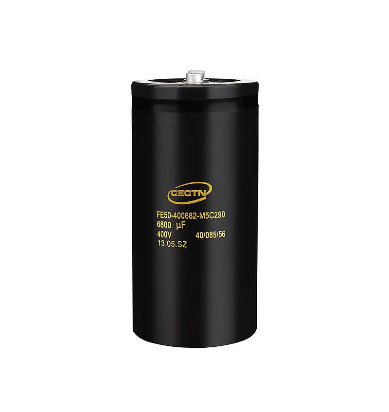
 400V 6800μF screw capacitor
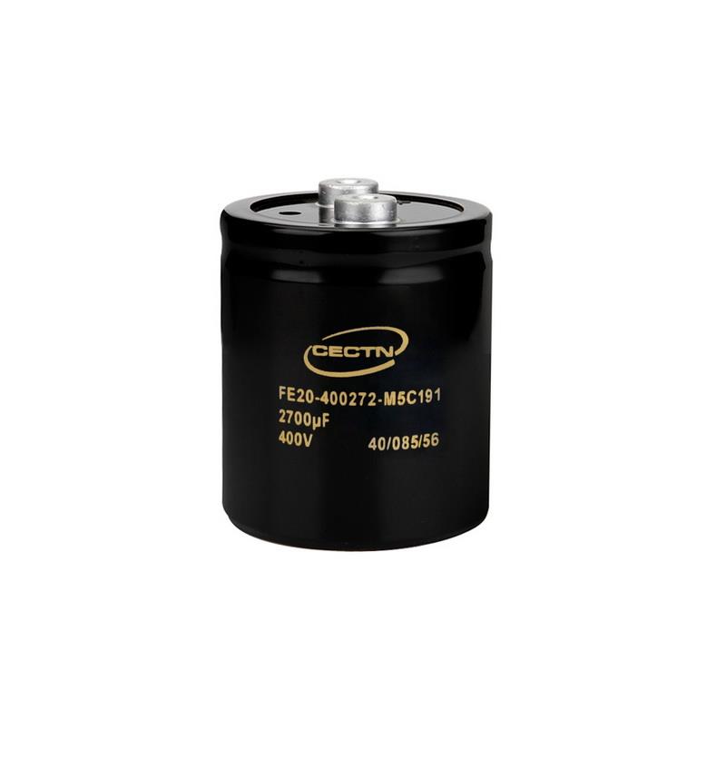
 400V 2700μF screw capacitor
 中文版
中文版