Calculation formula of service life of aluminum electrolytic capacitor with bolt
 Scan!
Scan!
Electrolytic capacitor service life (also defined as service life and working life) refers to the life that can be achieved when the failure rate of aluminum electrolytic capacitor does not exceed the specified value. The total failure or expected failure variable constitutes the end of service life.
Depending on the circuit design, device failure caused by parameter variables does not necessarily mean equipment failure. This means that the actual life of aluminum electrolytic capacitor may be longer than the given service life. The data of service life come from industry experience and accelerated test.
Operating the capacitor under the load lower than the rated value (such as lower working voltage, current and ambient temperature) and adopting appropriate heat dissipation measures can prolong the service life. In addition to standard series, kaiqijia can also provide other life grade aluminum electrolytic capacitors according to customers special requirements.
1. Load condition of aluminum electrolytic capacitor
IEC defines the service life of capacitors with liquid electrolyte (electrolyte formula owned by kaiqijia with independent intellectual property rights) based on the following conditions:
--Rated voltage
--Rated ripple current (peak value of AC voltage superimposed on DC voltage shall not exceed rated voltage)
--Rated temperature
2. Heat dissipation of aluminum electrolytic capacitor
The service life stated in the specification of electrolytic capacitor refers to the service life under the condition of natural heat dissipation, that is, the heat generated in the core is dissipated by the shell and natural convection. Additional cooling methods such as radiators, water cooling and forced ventilation can be used to increase the allowable ripple current and / or extend the service life. On the contrary, reducing heat dissipation (such as densely arranged capacitor banks, thermal insulation packages and too close vacuum layers) will reduce service life.
In order to reduce the thermal resistance between the core and the shell, kaiqijia sets a thermal bridge between the winding and the shell of its can capacitor.
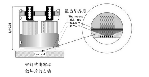
a. Use the bottom of the radiator to dissipate heat
Since most of the heat is dissipated through the bottom of the shell, installing a radiator at the bottom of the capacitor is the most effective way to dissipate heat. For the installation of heat sink, kaiqijia designed a specially optimized bolt type high voltage capacitor to ensure better heat transfer between the bottom of the shell and the heat sink. The special design includes: two bottom cooling pads. The first pad (0.5mm thick) is close to the air gap in the area not covered by insulating sleeve at the bottom, and the second pad (0.2mm thick) ensures the electrical insulation at the bottom.
Especially when multiple capacitors are installed between the radiator and bus bar, the total length of capacitor L1 (± 0.35mm) with minimum tolerance can avoid unnecessary mechanical stress on the terminal.
There are additional slots on the bottom edge of the shell, which can be used for the installation of the ring clamp ~FKC03)。 The ring clamp ensures the connection between the housing and the radiator.
b. Forced air cooling
When using forced air cooling, it must be remembered that the installation position can only affect the thermal resistance between the capacitor housing and the surrounding air. In the case of natural convection, the thermal resistance is greater than that between the core and the shell.
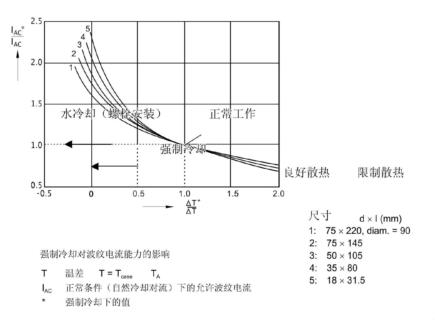
The thermal resistance is proportional to the temperature difference △ t. The user can measure the temperature difference (tcase TA) under normal condition and forced air cooling (△ t *) and load condition under constant ripple current, and then calculate the corresponding decrease and increase of thermal resistance from forced air cooling coefficient △ t * / △ t. In turn, the forced air cooling coefficient can be used to determine the ripple current coefficient IAC * / IAC. The latter is the measurement method that the maximum ripple current can be achieved by forced air cooling without reducing the service life.
The figure below shows the influence of forced air cooling coefficient on ripple current coefficient IAC * / IAC of different shell sizes (obtained by measurement). In this figure, the service life of the capacitor under forced air cooling (ripple current load: IAC *) has been converted into the service life of the aluminum electrolytic capacitor under normal working conditions (ripple current load: IAC).
The following table is a typical value of forced cooling fineness, which can be obtained by forcing the corresponding air velocity.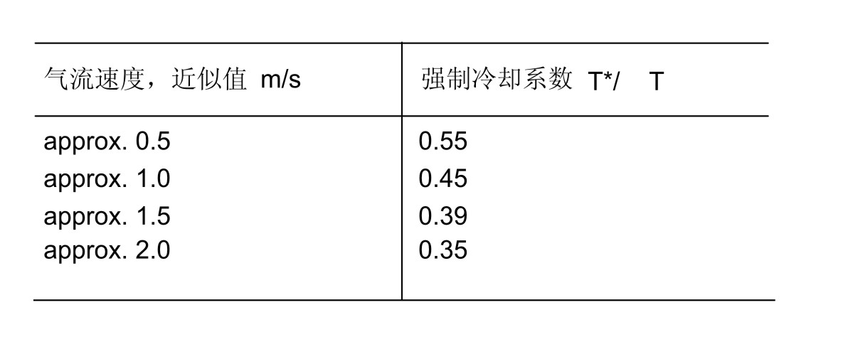
The forced cooling coefficient can be reduced to zero or even negative value when using cooling liquid (such as water or oil) with lower temperature than ambient temperature. Because of the thermal conductivity of these media, the linear law of pure thermal resistance is no longer applicable. In these cases, the forced cooling coefficient is also a function of the power consumption of the electrolytic capacitor itself. If this cooling measure is used, the maximum possible heat load must be calculated. If only radiator and forced convection are used, it is unnecessary to consider.
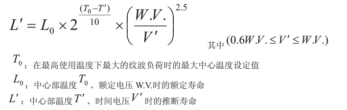
3. Calculation of service life of electrolytic capacitor
A separate specification lists the rated ripple current IAC, R at 100Hz at the upper temperature (+ 85 ℃, + 105 ℃ or + 125 ℃). The known core temperature (the core temperature can also be indirectly calculated by ripple current load, ambient temperature, wind speed and other parameters) and the service life under working voltage depend on the following service life formula:


同类文章排行
- 200V470uF Bullhorn Electrolytic Capacitor Package Size
- What are the specifications of 315V1000uF bullhorn electrolytic capacitor?
- What are the specifications of 200V470uF bullhorn electrolytic capacitors?
- 315V1000uF bullhorn type aluminum electrolytic capacitor package size
- CECTN brand bullhorn electrolytic capacitor material number description
- CECTN aluminum electrolytic capacitor material number description
- What are the package sizes of 200V1800uF bullhorn electrolytic capacitors?
- Bolt capacitor specification_Bullhorn electrolytic capacitor specification table
- Horn electrolytic capacitor soldering pin style description
- Bolt Aluminum Electrolytic Capacitor Terminals Description
最新资讯文章
- 250V 4700μF screw capacitor
- 250V 22000μF screw capacitor
- 250V 15000μF screw capacitor
- 300V 18000μF screw capacitor
- 300V 27000μF screw capacitor